(AKA Expanding a Manncorp/Autotronik MC384V2 to use Siemens Siplace feeders.)
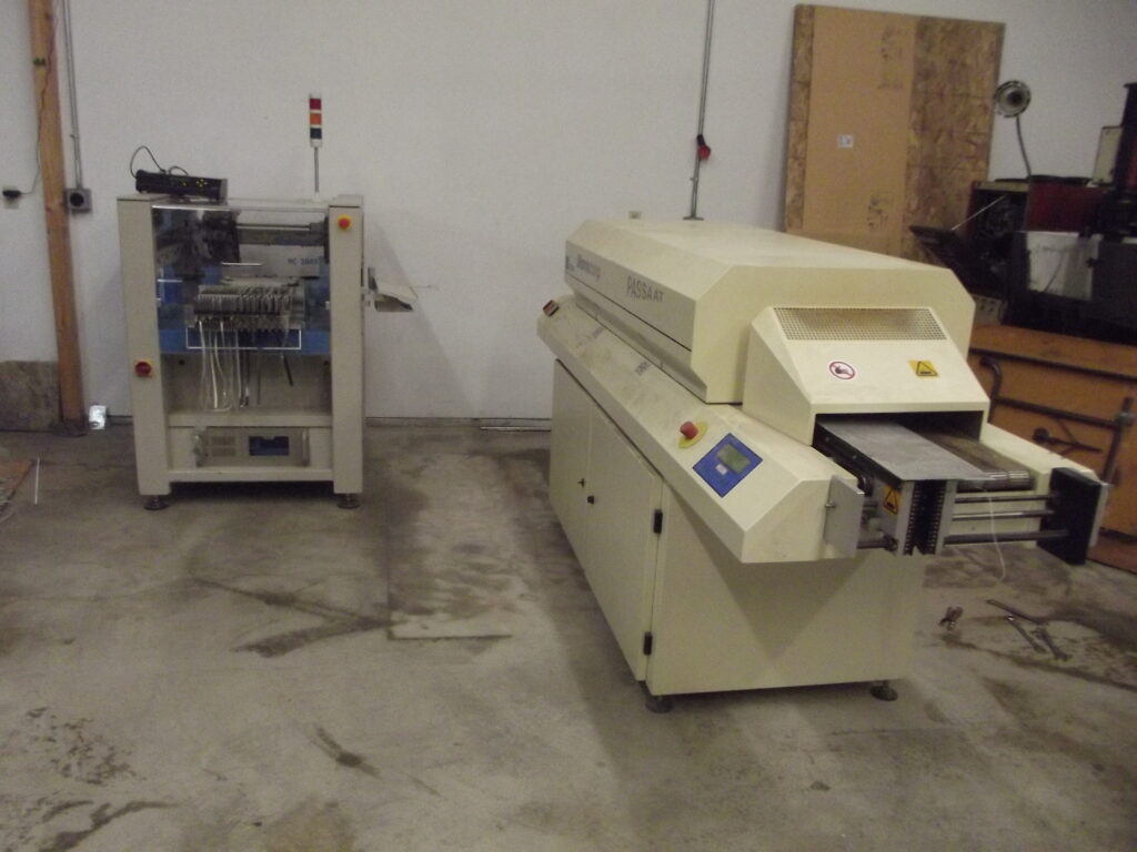
Years back we ended up with a Manncorp MC384V2 along with a few other Manncorp branded items such as ovens and paste stencil. Lucky for us these mostly came with spare parts and manuals/docs/software. The machine had very few hours as it was not used significantly before being stored for years but needed the typical service and setup.
After making some calls to Manncorp I basically determined I had hit a brick wall. They would not sell me parts or assist with service unless I had a “Service contract” with them. Since my machine was “too old” they would no longer support it nor would they offer any service. This was not a major issue to me as far as parts/hardware go since I can typically find those items (or make them) if needed. My only issue was the service/setup codes which allowed full calibration of the machine. Without them you could not get into the lower level settings. I had the generic operators code which is well known online (9182) but if you attempt to use this code for some of the other calibration items in the menu it will give an error.
Until one day…I noticed inside the machine, written on a rail in red sharpie was “918228”.
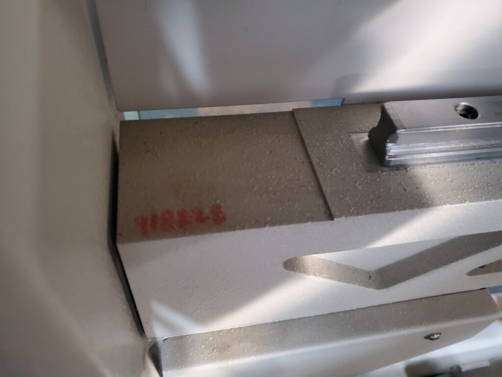
Aha…yep…you guessed it. They just reversed and repeated the last 2 digits for the service access code.
At this point I realized I could get where I needed to be and then some.
A bit later, after getting the machine up and running. I was producing V2 Smoothieboards and I had the inconvenience of not having nearly enough feeders for the board. I had less than 30 when I needed at least 30 more 8mm as well as several 12/16/24mm feeders. The machine can hold/address up to 128 autofeeders, as well as, tray positions (limited to 50, IIRC).
So my first thought was to make 3d printed holders for the tape so I could put parts which were 1 or 2 positions per board in the side feeders and just do a manual move after every couple runs.
This “worked” but very badly. The primary issue is the way the machine is coded to function. if it picks up a part from an “autofeeder” and rejects it then it drops the part in a small bin…but if it picks up from a “tray” then it will attempt to set the part back down where it initially picked it from. This led to the trays getting bumped and scattering small parts.
These feeders seemed to work fine for larger parts but for the 0402/0603 parts it was mostly unusable.
This led to me hand placing over 30 distinct 0402 parts (in various counts) as well as some larger parts by hand under magnification. Which was increasing my time by 30+ minutes per board. I did over 200 boards this way.
In my eyes…this was unacceptable.
Once again I bit the bullet and called Manncorp to see what it would cost to expand the bays since they still use the same feeders on their current machines.
Again I was told that due to the age of the machine they did not want to do anything with it…but “since the feeders were like another machine purchase they could do that”.
The quote I got over the phone was ~$32k (minimum) to add another 32 feeders along with the “bay” which holds them in place. This cost was before taxes, shipping…etc.
Since they could finance this I took it into serious consideration. 30min/board of hand placing starts to eat up a lot of shop time. Since the PnP can do in <10min what takes me 30+ it does not take long to recoup $32k.
While researching I decided to look into what OpenPNP was using for their feeders and I came across the work of Bilsef and his feeder controller which converts standard Gcode into the necessary data to drive and access the Siemens Siplace feeders.
https://github.com/bilsef/SchultzController
Since Smoothieware is a gcode interpreter and I knew it also has the ability to send gcode to the console when a pin is triggered I started to get an idea in my head.
Maybe I could make these Siemens feeders work in place of the Autotronik feeders.
Siemens 3x8mm feeders are widely available on the market (due to age they are often scrapped) whereas the Autotronik ones don’t seem to come on the market often and when they do they tend to be expensive.
So. I began the testing.
First step was to determine the signal used to “advance” the feeder. This was the main/only “necessary” thing to have. At this point I assumed it was a serial data signal that the “smart feeders” interpreted as commands. I knew if I could decode the signal it would be trivial to intercept/repeat the signal and make it trigger Bilsef’s level shifter board.
After hooking up a DB9 breakout board to a DSO I found that everything was much easier than that. The machine did not send a “data packet” for the commands but instead just sent a 20ms low pulse to a pin on the feeder.
This was great news. This meant that I could directly connect the output pins to a Smoothieboard V2 which would convert the low pulse into a Gcode string which would then be sent to Serial. Then I figured I could either go through a USB on a raspi or PC and then send that out to Bilsef’s controller board and it’s “Nano every” MCU.
After acquiring some feeders and building a few of Bilsef’s controller boards for testing I started off on the plan.
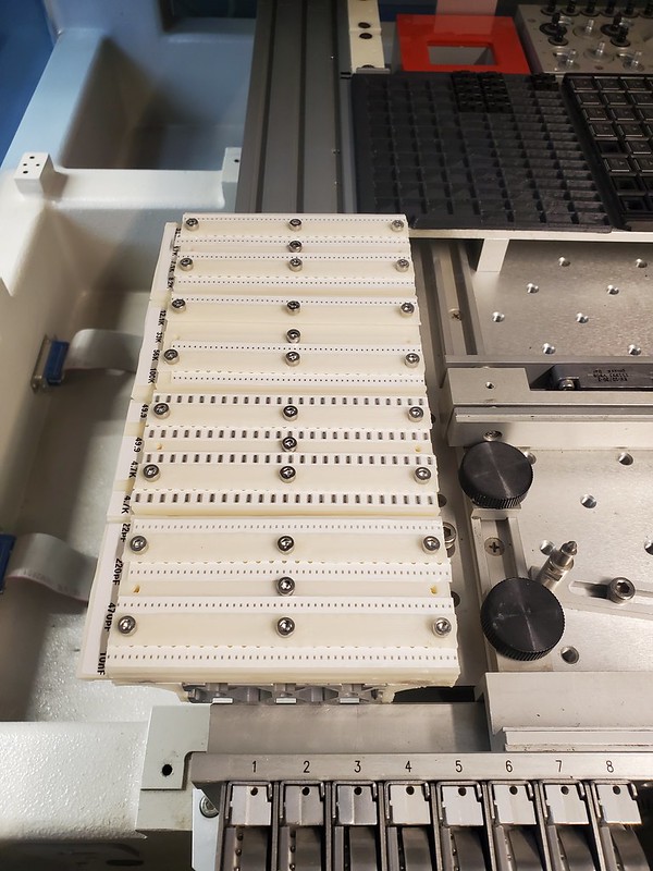
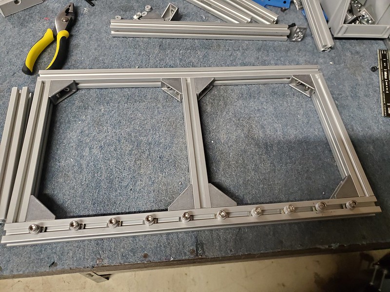
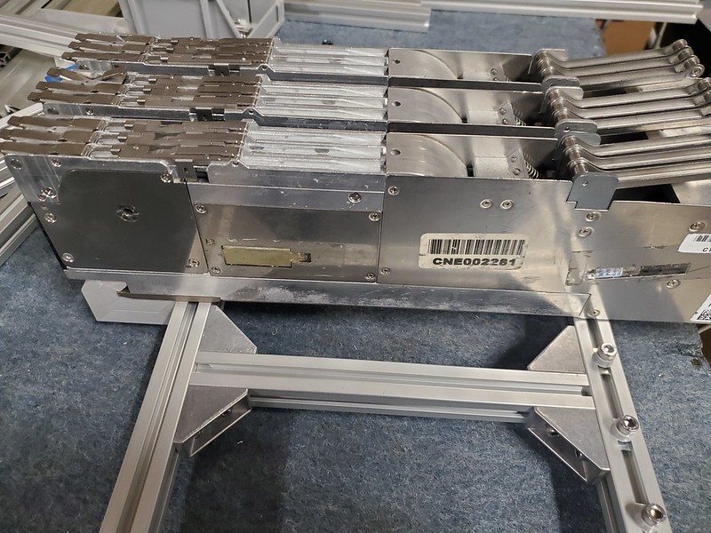
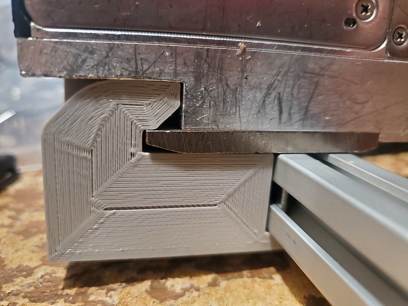
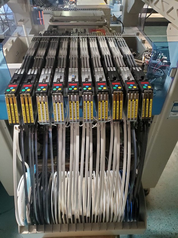
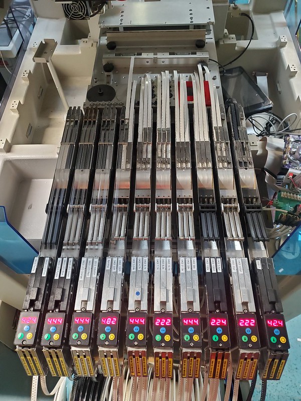
I built a rack which held the feeders and designed some 3d printed mounts to allow them to easily be removed from the rack.
Next step was to get some DB25 adapters so I could plug into the machine and attempt to map out the pinout for the feeders. Using a DMM and the schematics I was able to map out which pins did what on the output of the Manncorp.
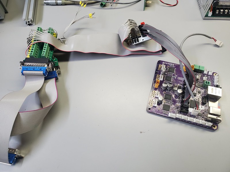
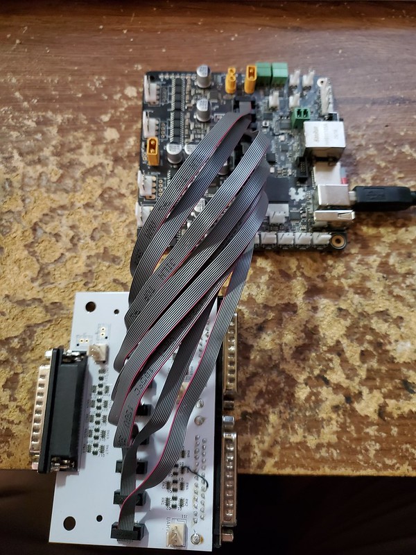
I built a very messy adapter cable which went to a pair of adapter boards and connected those to the V2 Smoothieboard through the gadgeteer headers and began planning my config file for the Smoothieboard to make this all work.
I ran all this by Wolfmanjm. He informed me that this may cause issues with smoothie as some of the commands would mess with the console the way they were by default.
This seemed a bit discouraging…I figured I could do some creative renaming and make it happen…then he told me that he had planned to make the firmware have the ability to “steer” the commands through UART0 or UART1 instead of through the debug (UART2). This solved that issue immediately.
Since this was something that not only helped me but was useful later in the firmware he added it to the main branch. I can see it being very handy and I plan on using this feature more.
https://github.com/Smoothieware/SmoothieV2/wiki/New-features#uarts
Then he reminded me that not all the pins on the V2 board that are available are 5v capable.
https://github.com/Smoothieware/SmoothieV2/wiki/Pins#not-5v-tolerant
Ug…this meant I needed to redo my entire pin mapping to the inputs and it also limited a bit of the available pins on the smoothie. It was quite a mess initially but it functioned. Electrically, everything was tied in to get signals from the Manncorp to the Smoothieboard.
Now to get the signal from the Smoothieboard UART1 to Bilsef’s controller board.
This took a bit of research.
First, I loaded the files from the Nano Every into Kicad and began to find what needed to be done.
The nano every uses a USB chip which is level shifted and then sent to the “main MCU” which has the code onboard.
After cutting the TX>RX line between these 2 and then hooking in before the level shifter I was able to directly take the TX line from the Smoothieboard and run that signal into the Nano’s main MCU.
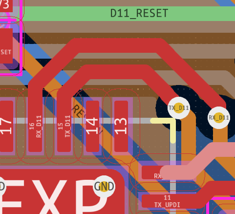
Since the Nano every uses UPDI for uploading code…this should not interfere with the ability to reflash via usb…but will not allow use of the USB to communicate with the “code”. After a bit of testing I was able to use Smoopi host to send commands through the Smoothieboard directly to the feeders. This was a big success.
Next, my plan was to use the “switch module” in Smoothieware to do a simple “if triggered, send string” but Wolfmanjm pointed out that the new “buttonbox” module was a much better fit for what I was doing in the config. Not only that but with this module you can make the trigger be “on press” or “on release” which is very handy. (Wolfmanjm also edited this module to make it more functional based on my needs, much respect is deserved for his work)
https://github.com/Smoothieware/SmoothieV2/wiki/New-features#button-box
Once this was configged I had some issues with the triggers being random and also they “felt” like it was happening during the high pulse instead of the low pulse.
Wolfmanjm yet again to the rescue. He edited the firmware again to adjust the window of which a pulse can be seen in the firmware (debounce/timing related) which made it a bit cleaner but it still “felt” to be triggering wrong. He looked at my config settings and realized I had neglected to invert the pin. I was attempting to have the disabled state as Low…not high. Whoops…easy fix just add a ! to the end of them all and it solved it.
Now finally, when I pressed the button to advance the feeder in the Manncorp software it would trigger the Siemens feeders.
Aside from the mess…there was an issue that if the Manncorp was turned off the outputs “float”. This would cause random triggers on the Smoothieboard input (basically antennas hooked to pins at that point) and since the internal pullups are 3.3v I could not use them while using the Manncorp’s 5v pullups (hardware).
So the easy solution was level shifters.
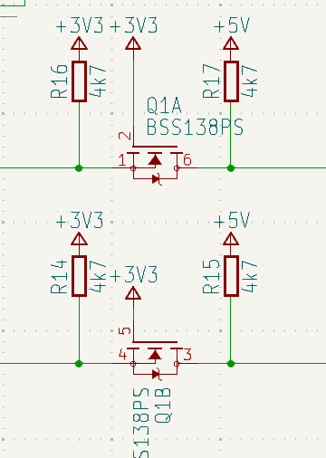
While working on the Nano every hack I noticed they were using the mosfet based level shifters similar to what Sparkfun used to sell.
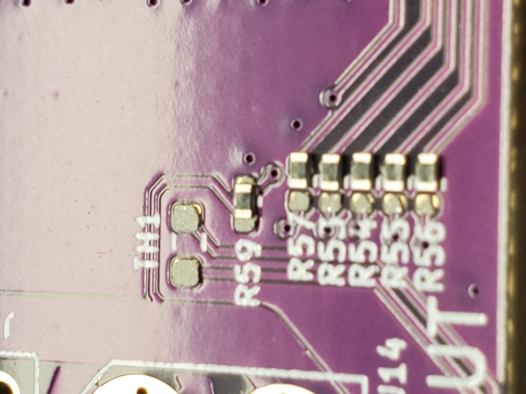
It is a neat circuit which makes a bidirectional level shifter from a single fet and a couple resistors. The thing they were doing though that was new to me was using a dual pack version of the mosfet.
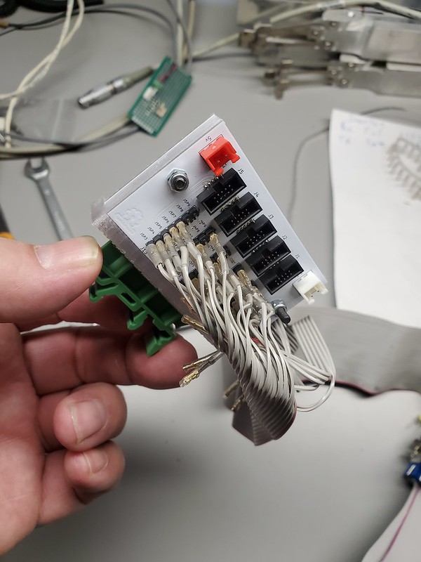
I decided to borrow the idea and made a level shifter design based around 2 of the fet pairs and 2 R-packs which makes a nice clean 4 channel bidirectional level shifter.
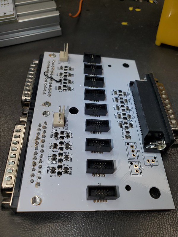
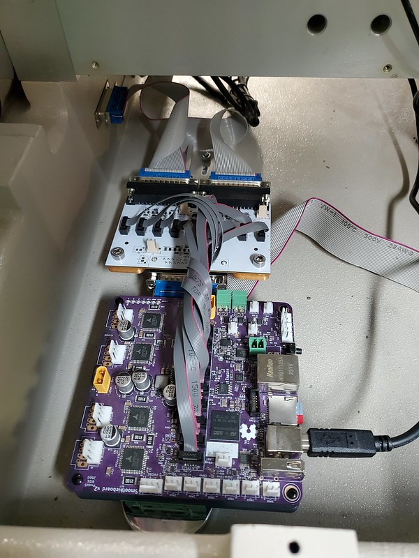
I designed a board to shift as many of the available GPIO pins on the Smoothieboard as possible. After skipping the pins which are shared by the SPI for the Motor drivers and the 4 pins reserved for the UARTs I still had 56 pins. So during this design I made it so it has 2 DB25 headers to get all 32 signals from the back bay position of the Manncorp as well as adding a single DB25 to get the first cable of the left side bay position. During research I realized the first DB25 header on each bay has more “active” pins so instead of 16 it gives over 20.
So the final board takes 3 DB25 connectors which come from the Manncorp and breaks out the necessary pins to level shifters for all GPIO, headers for UART1/2, Manncorp UART and 24v from the Manncorp.
So now I have 52 pins coming from the Manncorp to the Smoothieboard which can all be tied to their corresponding feeder, the UART setup to com to Bilsef’s controller board and the feeders in a mount holding them in the necessary location to be used by the machine.
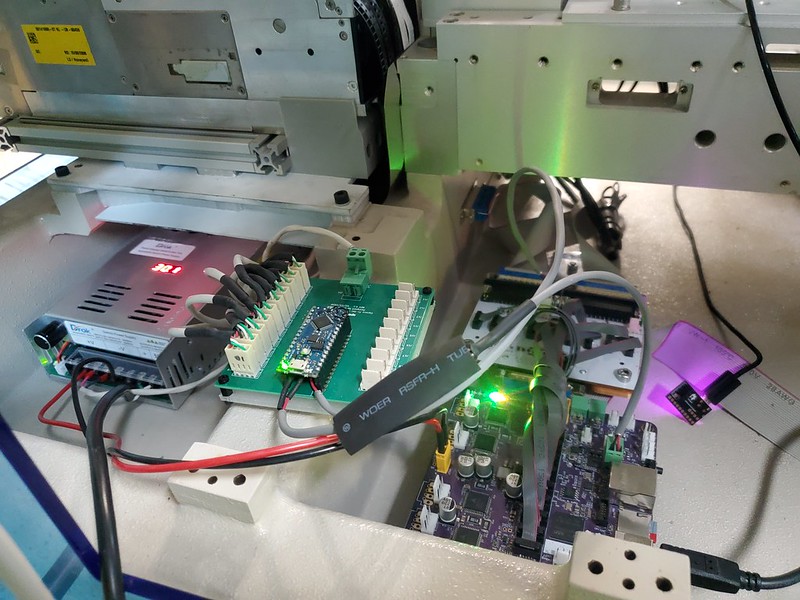
Ready to setup the Pick/Place program now.
After a couple days of setup and computer work all was ready to begin running some boards. This typically is a “tuning” experience. Often the first 5 or so runs can be a bit messy until everything is properly tuned in the pick, optical check and place. I call this “tuning” because you are very often editing slight settings such as vacuum, height, or setting up custom vision profiles for the footprints.
Once the first board is ran a full runthrough using the machine’s vision inspection is required and production placement needs to be adjusted on a per part basis. Basically, you look in the camera. If a part is not where it should be you adjust the crosshairs to where it is and it will make a XY adjustment in the placement record and the next time that part is placed it will be where it needs to be in XY as well as rotation.
This can take a few boards to get everything perfect.
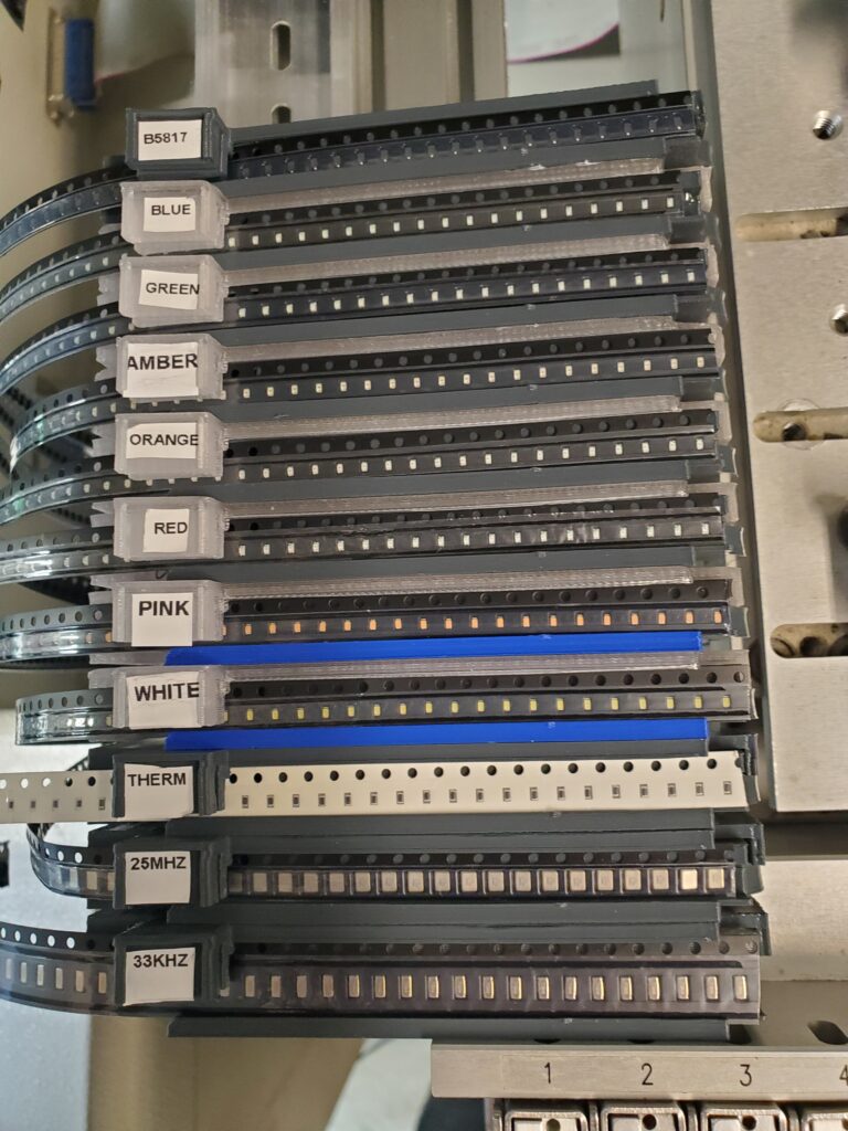
After running a small batch I am now ready to continue on full scale production. All the feeders which I installed are working well. There is still a bit of tuning that needs to be done but it has nothing to do with the mod but is mostly related to “in machine” settings such as vision.
I also have another 5 of the 3x8mm feeders which I will be adding to the side of the machine and I plan on acquiring some of the 12/16mm feeders to go with them.
At this moment I am still hand placing a few parts but it is down to less than 10min per board…and that is including pre reflow inspection.
After everything, I have spent ~$2.5k on this mod which at the moment means 45 lanes of 8mm. The expansion board I designed allows for future mods possibly allowing for conveyors, shaker feeders and other accessories which were available as expansions to this PnP. (More stuff they said I couldn’t do 🙂 )
I love the fact that not only am I using a Smoothieboard in the machine that makes Smoothieboards…but also that this entire hack was made available by “the big wheel of opensource”.
Smoothieware led to Smoothieboards. Smoothieboards/Smoothieware was used to initially develop OpenPnP. OpenPnP development led to Bilsef’s controller board. Which was used to do this mod to build more Smoothieboards.
Without all those steps and the work of all the developers in these projects (as well as the projects that led to these projects. GRBL, Kicad, etc) I would not have been able to do these mods. Never forget that the things you build may lead to other things.
With any luck someone will need/use this info you just read as well.
Thank you to all who develop and support Opensource.
Chris Cecil,
Robosprout